Dev Diary - Generating ADF Data Flow Mapping using Biml
August 18, 2021
The work to generate Data Flow Mappings in Azure Data Factory using the BimlFlex automation platform is nearing completion. While there is still more to do, there are also a lot of topics that are worth sharing ahead of this release.
The BimlFlex solution, as a collection of designs, settings, configurations and customizations is provided as Biml patterns that can be accessed from BimlStudio. This means that a dynamic preview of the expected (generated) output is visualized in BimlStudio, along with the supporting Biml code.
At this stage, and if required, BimlStudio allows for further customizations using Extension Points, which support a combination of Biml script, SQL or .Net code. These will become part of the data logistics solution that will be deployed.
The build process in BimlStudio will ‘compile’ the Biml code into native artefacts for the target platform and approach. In the case of this development diary, this will be as Data Flow Mappings for Azure Data Factory.
Using Data Flow Mappings has certain advantages (and disadvantages) compared to moving and transforming data using other Azure Data Factory components such as Copy Activities. Much of the remaining work to complete this feature is about finding the best mix between the available techniques, so that these can be generated from the design metadata.
One of the advantages of using Data Flow Mappings, aside from the visual representation of the data logistics, is the ability to use inline Sources and Sinks (targets). Inline datasets allow direct access to many types of data sources without a dedicated connector object (dataset). They are especially useful when the underlying structure may evolve. Also, and especially in data lake scenarios, they offer a way to manage where the compute takes place without requiring additional compute clusters.
It is an easy and fast way to use a variety of technologies.
In this post, and the subsequent posts as well, we will use this approach as a way of explaining working with Data Flow Mappings in BimlFlex.
Biml Data Flow Mapping syntax
Because the design metadata is provided as Biml script, it makes sense to start explaining the BimlFlex Data Flow Mapping support in BimlStudio because this is the best way to work with the Biml language.
Defining a Data Flow Mapping using Biml is easy. The various features, components and properties available in Data Flow Mappings are supported as Biml XML tags.
A Data Flow Mapping is referred to by using the MappingDataFlow segment. It is part of the Dataflows, which is in turn part of a DataFactory.
Consider the example below:
<Biml xmlns="http://schemas.varigence.com/biml.xsd">
<DataFactories>
    <DataFactory Name="bfx-dev-deltalake-demo">
        <Dataflows>
            <MappingDataflow Name="HelloWorld">
                <Sources>
                    <InlineAzureSqlDataset
                        Name="HelloWorldExampleSource"
                        LinkedServiceName="ExampleSourceLS"
                        AllowSchemaDrift="false"
                        ValidateSchema="false"/>
                </Sources>
                <Sinks>
                    <InlineAzureSqlDataset
                        Name="HelloWorldExampleTarget"
                        LinkedServiceName="ExampleTargetLS"
                        SkipDuplicateInputColumns="true"
                        SkipDuplicateOutputColumns="false"
                        InputStreamName="HelloWorldExampleSource.Output"/>
                </Sinks>
            </MappingDataflow>
        </Dataflows>
        <LinkedServices>
            <AzureSqlDatabase Name="ExampleSourceLS" ConnectionString="data source=example.com;"></AzureSqlDatabase>
            <AzureSqlDatabase Name="ExampleTargetLS" ConnectionString="data source=example.com;"></AzureSqlDatabase>
        </LinkedServices>
    </DataFactory>
</DataFactories>
In this ‘Hello World’ example, a single Data Flow Mapping is created with a single Source and a single Sink. Both the Source and the Sink are defined as inline datasets, which are specific options in Biml to distinguish them from regular datasets.
Inline datasets require a connection (Linked Service) to be assigned, and for a valid result this Linked Service must also be available.
When using BimlStudio to interpret this snippet, these components will be visible in the Logical View:
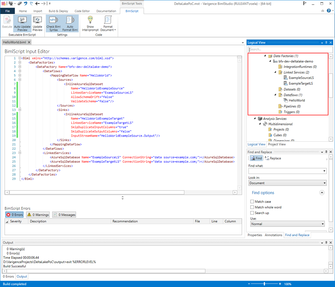
This skeleton code shows how Biml supports Data Flow Mappings, and inline data sources in particular. In the next post, we will expand this into a larger pattern and then look into how BimlFlex configurations influence this output.