Varigence Blog
Dev Diary - First look at a source-to-staging pattern in Mapping Data Flows
The 2021 BimlFlex release is being finalized, and will be available soon. This release contains a preview version of Mapping Data Flow patterns that can be used to generate this type of output from BimlFlex. The corresponding (and updated) BimlStudio will of course have the support for the full Mapping Data Flow Biml syntax.
The first pattern you will be likely to see is the loading of a data delta from a source into a Staging Area and an optional Persistent Staging Area (PSA). Whether a PSA is added is controlled by adding a PSA connection to the project that sources the data. So, adding a PSA connection will add a PSA to the process, unless overridden elsewhere.
Conceptually, the loading of data into a Staging Area and PSA are two separate data logistics processes. For Mapping Data Flows, these are combined into a single data flow object to limit the overhead and cost involved with starting up, and powering down, the Integration Runtime. Data is loaded once and then written multiple times from the same data flow. This approach is something we'll see in the Data Vault implementation as well.
This means that a source-to-staging loading process has one source, and one or two targets depending if the PSA is enabled. BimlFlex will combine these steps into a single Mapping Data Flow that looks like this:

This is by no means the only way to load data from a data source into the solution. Especially this layer requires various ways to load the data, simply because it can not always be controlled how the data is accessed or received. Potentially many limitations in applications, technology, process and organization apply - and this drives the need for different patterns to cater for different systems and / or scenarios. The staging layer is often the least homogenous in terms of approach for the data solution, and the full BimlFlex solution will see a variety of different patterns driven by settings and configurations.
If we consider this particular pattern, we can see that the PSA is used to check if data is already received. If no PSA is available, the data is just copied from the source into the (Delta Lake) Staging Area.
The validation whether data is already available is done using a Lookup transformation. The lookup compares the incoming record (key) against the most recent record in the PSA. If the incoming key does not exist yet, or it does exist but the checksums are different, then the record is loaded as data delta into the Staging Area and also committed to the PSA. 'Most recent' in this context is the order of arrival of data in the PSA.
At the moment the supported sources and targets for this process are Azure SQL databases and Delta Lake, but the Biml language now supports all connections that are provided by Azure Data Factory and Mapping Data Flows so more will be added over time.
However, using Delta Lake as an inline dataset introduces an interesting twist in that no SQL can be executed against the connection. This means that all logic has to be implemented as transformations inside the data flow. For now, the patterns are created with this in mind although this may change over time.
The most conspicuous consequence of this requirement is that the selection of the most recent PSA record is implemented using a combination of a Window Function and Filter transformation. The Window Function will perform a rank, and the Filter only allows the top rank (most recent) to continue.
Over the next few weeks we'll look into more of these patterns, why they work the way they do and how this is implemented using Biml and BimlFlex.
Dev Diary - Integration with the BimlCatalog
Every data solution benefits from a robust control framework for data logistics. One that manages if, how and when individual data logistics processes should be executed. A control framework also provides essential information to complete the audit trail that tracks how data is processed through the system and is ultimately made available to users.
Working with Biml via either BimlExpress or BimlStudio provides the language, compiler, and development environment to create your own data solution frameworks from scratch, which means the control framework must be defined also.
BimlFlex has the advantage that that the output that is generated is already integrated with the proprietary control framework that is provided as part of the solution: the BimlCatalog. The BimlCatalog is the repository that collects runtime information and manages the registration of individual data logistics processes. It is used to control the execution and provides operational reporting on the overall loading process such as run times and success / failure rates.
The BimlCatalog is available freely and can be integrated with your own custom solution – for example using BimlExpress. However, when using BimlFlex the integration of the patterns with the BimlCatalog is already available out of the box. This is the topic of today’s post.
BimlCatalog integration for Mapping Data Flows
The BimlCatalog classifies data logistics as either an individual process or a batch. A batch is a functional unit of execution that calls one or more individual processes. Processes can either be run individually, or as part of the batch if one is defined. In Azure Data Factory, a batch is essentially an Execute Pipeline that calls other pipelines.
To inform the control framework of this, a flag that labels a process as a batch is passed to the stored procedure that is provided by the BimlCatalog. This procedure, the LogExecutionStart also accepts the execution GUID, the name of the process and the project it belongs to as input parameters.
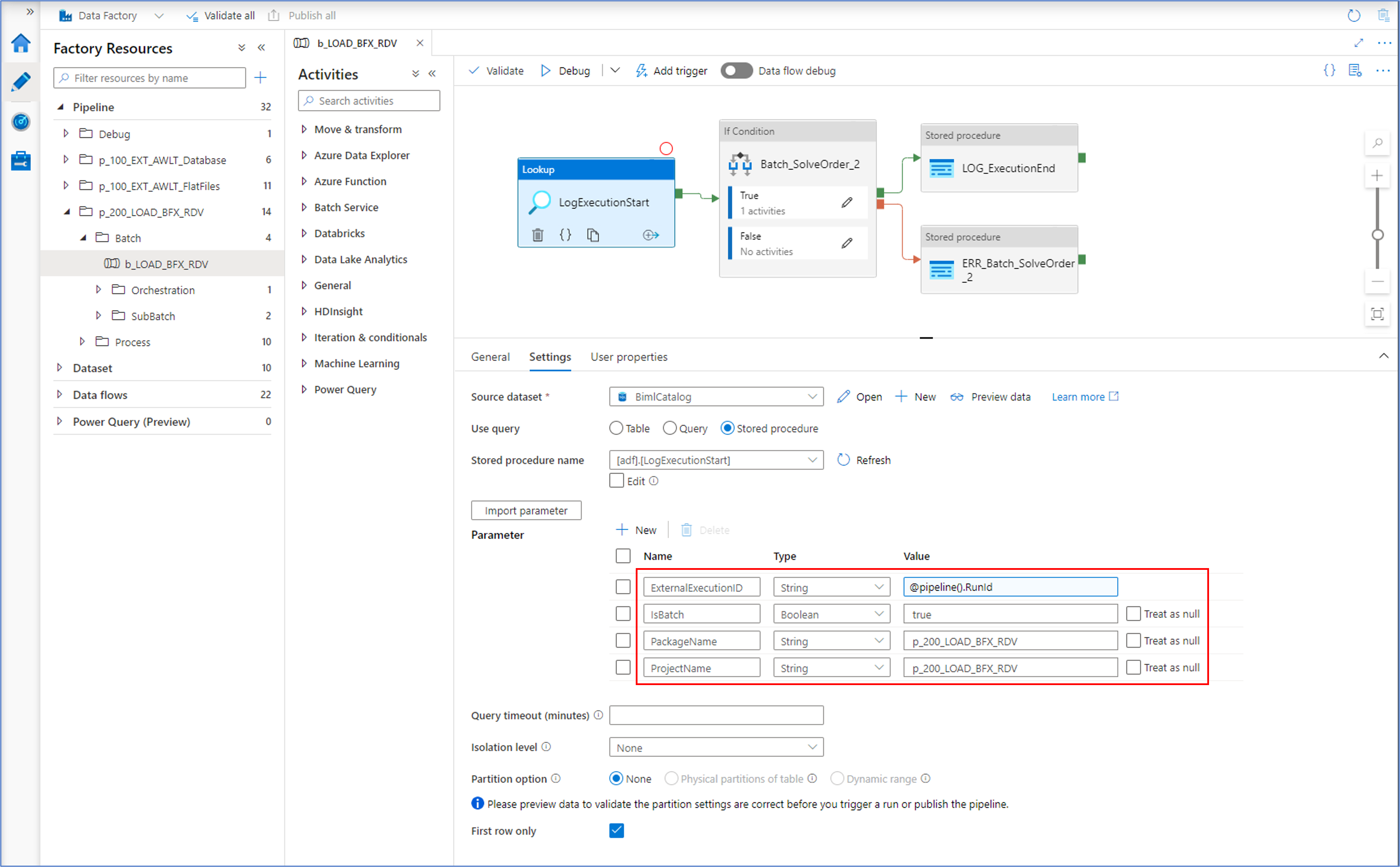
The LogExecutionStart will run a series of evaluations to determine if a process is allowed to be run, and if so under what conditions. For example, an earlier failure may require a clean-up or it may be that the same process is already running. In this case, the control framework will wait and retry the start to allow the earlier process to complete gracefully. Another scenario is that already successfully completed processes that have been run as part of a batch may be skipped, because they already ran successfully but have to wait until the remaining processes in the batch are also completed without errors.
After all the processes are completed, a similar procedure (LogExecutionEnd) informs the framework that everything is OK.
A similar mechanism applies to each individual process, as is visible in the screenshot below.
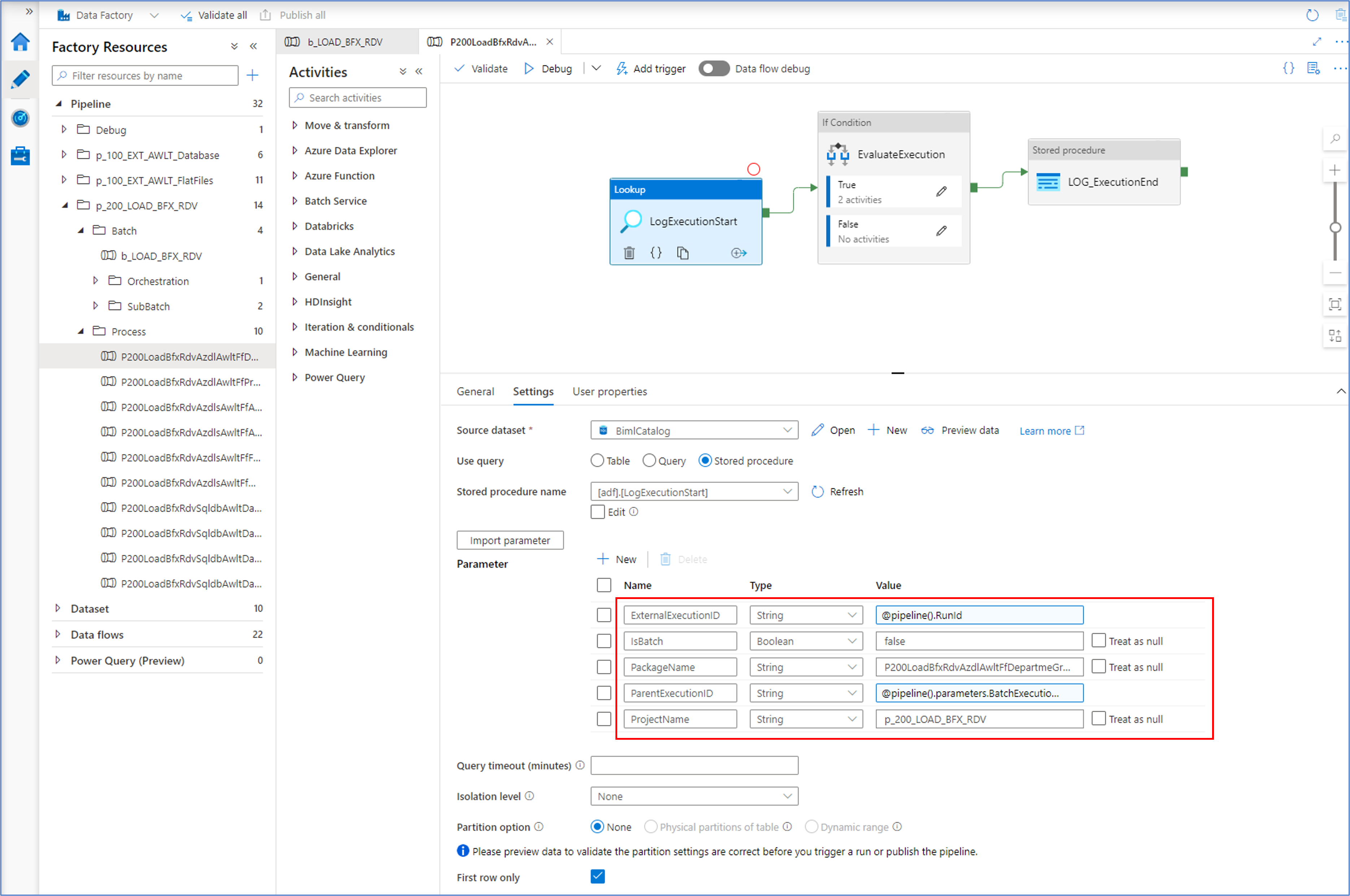
In this example, the IsBatch flag is set to 'false' as this is not a process that calls other processes. Similarly, a parent execution ID is provided - the runtime execution ID of the (batch) process that calls this one.
In case something goes wrong
So far, the focus of the control framework integration has been on asserting a process can start and under what conditions. However, it is important to make sure that any failures are handled and reported. This is implemented at the level of each individual process.
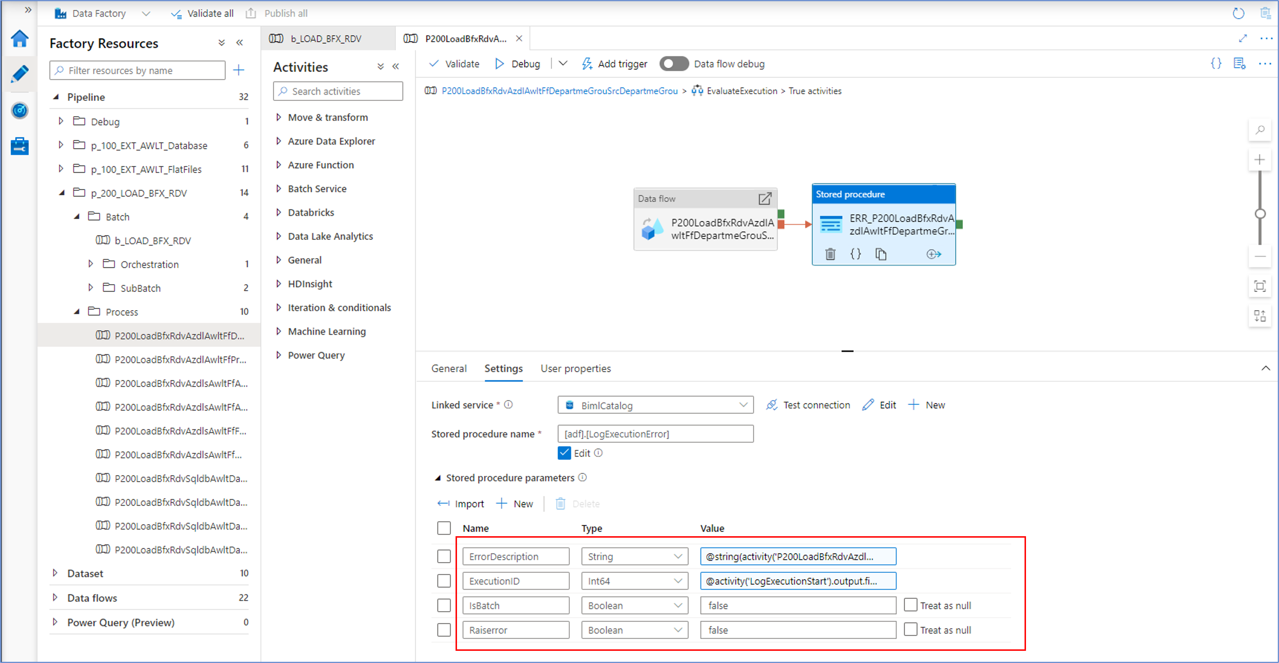
Each individual execute pipeline that calls a Mapping Data Flow will report any errors encountered by calling the LogExecutionError procedure. Within the BimlCatalog, this will also cause the parent batch to fail and inform subsequent processes in the same batch to gracefully abort. The batch will preserve the integrity of the data for all processes it encapsulates.
Dev Diary – Orchestrating Mapping Data Flows
Earlier dev diary posts have focused on defining and deploying a Mapping Data Flow using Biml. For example, covering the Biml syntax and adding initial transformations and parameters.
Additional complexity will be added in upcoming posts to ultimately cover a fully functioning set of patterns.
These Mapping Data Flows can be generated from BimlFlex by selecting the ‘Azure Data Flow’ Integration Template for a Project. The Project defines which data sets are in scope for a specific deliver or purpose, and the Integration Template directs the automation engine as to what output is required – Mapping Data Flows in this case.
The settings, overrides and configurations govern how the resulting output will be shaped and what features are included in the resulting Mapping Data Flow.
One of these features covers the orchestration.
In Azure, a Mapping Data Flow itself is not an object that can be executed directly. Instead, it needs to be called from an Execute Pipeline. This pipeline can be run, and in turn it will start the data flow.
This means that a corresponding pipeline will need to be created as part of any Mapping Data Flow, and this is exactly what BimlFlex does out of the box. In addition to this, BimlFlex can use this pipeline to integrate the data logistics into the control framework – the BimlCatalog database. This database captures the runtime details on process execution, so that there is a record of each execution result as well as statistics on volumes processed and more.
An example of the generated output is shown in the screenshot below:
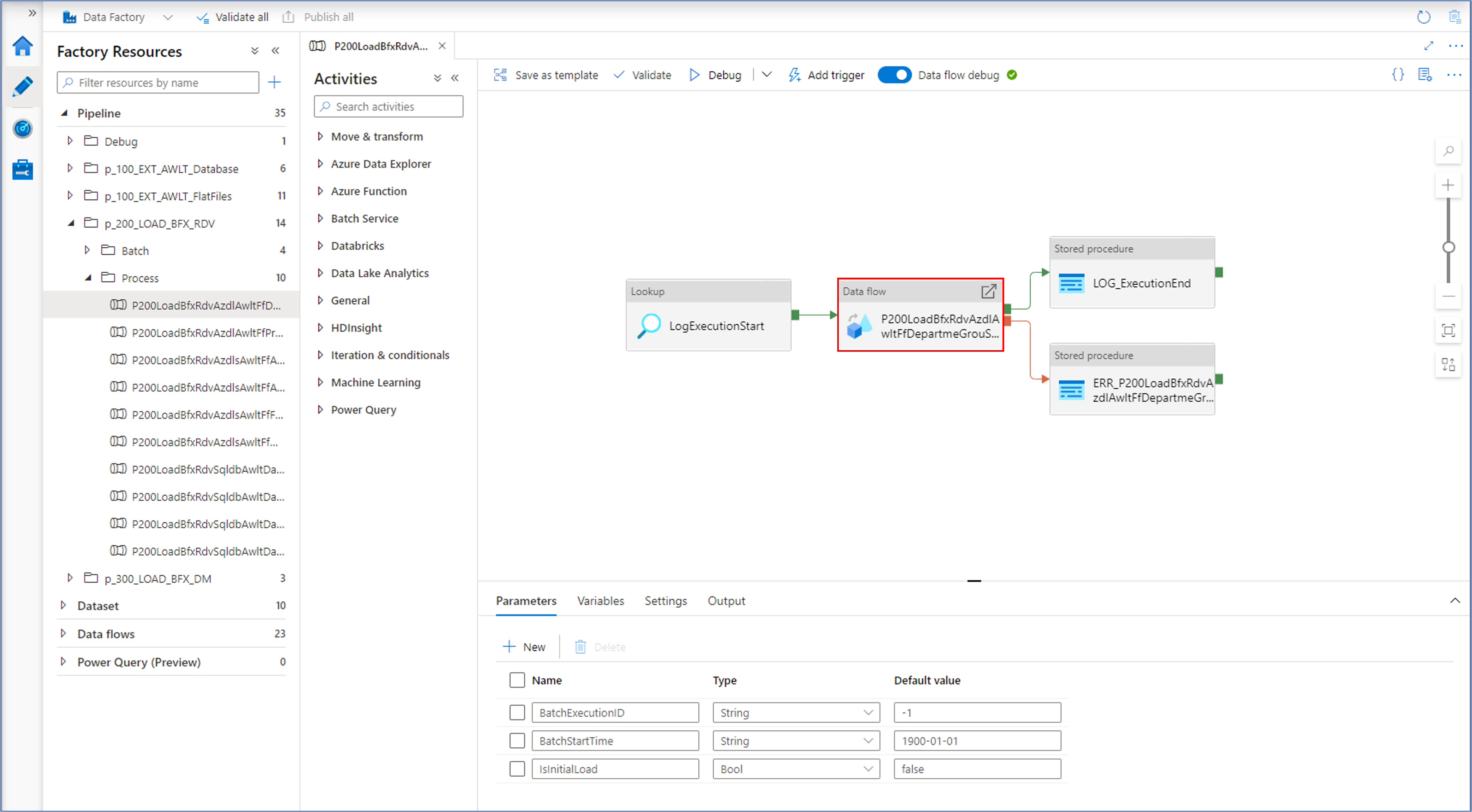
The BimlCatalog will also issue a unique execution runtime point that is passed down from the pipeline to the Mapping Data Flow where it can be added to the data set. This means that a full audit trail can be established; it is always known which process was responsible for any data results throughout the solution.
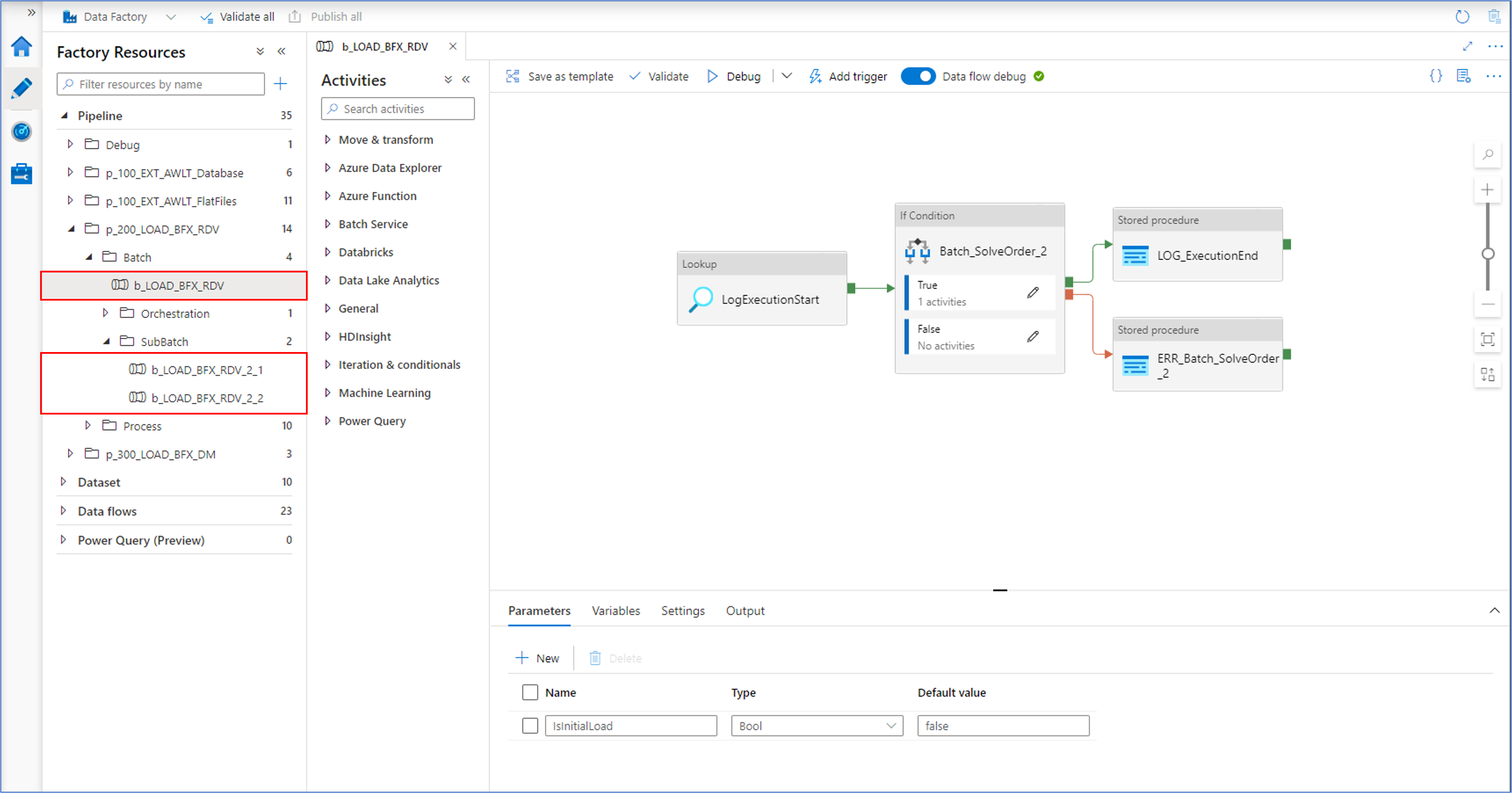
But BimlFlex will generate more than just the pipeline wrapper for the Mapping Data Flow and integration into the control framework. It will also generate a batch structure in case large amounts of related processes must be executed at the same time – either sequentially or in parallel.
To manage potentially large numbers of pipelines and Mapping Data Flows, BimlFlex automatically generates a ‘sub-batch’ middle layer to manage any limitations in Azure. For example, at the time of writing Azure does not allow more than 40 objects to be defined as part of a single pipeline.
BimlFlex will generate as many sub-batches as necessary to manage limits such as these, and each process will start the next one based on the degree of parallelism defined in metadata.
The next post will cover how to start generating this using Biml.
